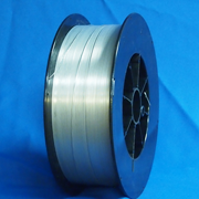
E347T-1

Class: E347TX-X
AWS: A5.22
Conforms to Certification: AWS A5.22 | ASME SFA A5.22
Weld Process: Gas Metal Arc
| AWS Chemical Composition Requirements | |
| C = 0.08 max | Si = 1.0 max |
| Cr = 18.0 – 21.0 | P = 0.04 max |
| Ni = 9.0 – 11.0 | S = 0.03 max |
| Mo = 0.75 max | Cu = 0.75 max |
| Nb = 8xC min – 1.0 max | Mn = 0.50 – 2.5 |
Available Sizes – Diameter X Spool Sizes
Available upon request contact us for more information
Application
This alloy is often referred to as a stabilized type 308 alloy. Electrodes of this classification usually are used for welding Chromium-Nickel steel base metals of similar composition stabilized with columbium or titanium. Following the chemical composition designation comes the letter “T” which signifies that the product is a flux cored electrode or rod. Following the “T” is a “1” or “0” indicating the recommended position of welding. The “1” or “0” following the “T” designates the following: “0” – designed to weld in the flat or horizontal position, “1” – designed to weld in all position. Following the position indicator and a dash, are the numerals “1”, “3”, “4”, “5”, or the letter “G”. The numerals “1”, “4”, and “5” identify the shielding gas required for classification of the electrode. The number “3” signifies that an external shielding gas is not employed. The letter “G” signifies that the shielding medium, chemical composition and mechanical properties are not specified.
| Deposited Chemical Composition % (Typical) | ||
| C = 0.05 | Mn = 1.20 | Si = 0.60 |
| Cr = 19.5 | Ni = 9.5 | Nb = 0.40 |
| Mo = 0.28 | S = 0.01 | P = 0.02 |
| Deposited All Weld Metal Properties % (As Welded) | |
| Tensile Strength | 85,000 psi |
| Yield Strength | 58,000 psi |
| Elongation | 35% |
Deposited Charpy-V-Notch Impact Properties %
Not applicable
Optimum Parameters |
Operating Range |
|||||
| Diameter | Position | Wire Feed Speed | Amps | Volts | Amps | Volts |
| 0.035 | Flat | 365″ / minute | 130 – 140 | 24 – 25 | 100 – 170 | 21 – 26 |
| 0.035 | Horizontal | 365″ / minute | 130 – 140 | 24 – 25 | 100 – 170 | 21 – 26 |
| 0.035 | Vertical – Up | 310″ / minute | 110 – 120 | 22 – 23 | 110 – 120 | 21 – 23 |
| 0.035 | Overhead | 320″ / minute | 120 – 130 | 23 – 24 | 120 – 130 | 22 – 24 |
| 0.045 | Flat | 450″ / minute | 180 – 200 | 25 – 27 | 135 – 250 | 24 – 32 |
| 0.045 | Horizontal | 450″ / minute | 180 – 200 | 25 – 27 | 135 – 250 | 24 – 32 |
| 0.045 | Vertical – Up | 325″ / minute | 150 – 170 | 24 – 26 | 135 – 200 | 24 – 26 |
| 0.045 | Overhead | 425″ / minute | 175 – 195 | 25 – 27 | 155 – 200 | 25 – 28 |
| 1/16 | Flat | 264″ / minute | 220 – 240 | 25 – 27 | 170 – 300 | 24 – 31 |
| 1/16 | Horizontal | 235″ / minute | 200 – 220 | 25 – 27 | 170 – 270 | 24 – 29 |
| 1/16 | Vertical – Up | 220″ / minute | 190 – 210 | 25 – 26 | 170 – 230 | 24 – 27 |
| 1/16 | Overhead | 235″ / minute | 200 – 220 | 25 – 26 | 170 – 270 | 24 – 29 |
For best results, set the wire feed speed and adjust the voltage for smoothest operation. Electrode extension range is from 1/2” to 1,” with an optimum range of 5/8” to 3/4.” Weld using reverse polarity DC(+).
Shielding Gas
75% argon / 25% CO2 (or nearest equivalent) shielding gas; however, straight CO2 may also be used. The 75/25 mixture will produce a smoother arc with virtually no spatter and slightly higher yield and tensile strengths than CO 2. The mechanical properties and deposit analyses will meet AWS A5.22 specifications with either gas.
